
Safety Barriers
Product Details · PRODUCT DETAILS
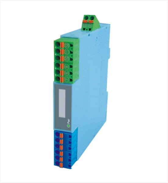
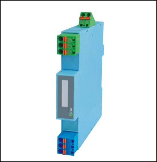
LU-BK22 Digital Output Isolation Safety Barrier (2 In / 2 Out)
Two-input, two-output digital output isolation safety barrier.
I. Overview
The LU-BK22 safety barrier controls field devices in the hazardous area through switch, transistor or logic level signal input from the power supply in the safe area. It is suitable for driving intrinsically safe devices such as solenoid valves and alarms, as well as other simple devices without energy storage.
Powered by an independent DC power supply, with isolation between power supply, input and output.
With high/low level status indicator lamps for the output signal
Compact unit, light weight, suitable for high-density installation
II. Technical specifications
Input parameters (safe area signals)
Input type
A. Dry contact switch selected: input current ≤3mA / 24V; switch delay ≤2s
B. Level signal selected: high level 4~24V; low level ≤1V
C. Transistor selected: electrical rating 30VDC, 100mA
Output parameters (hazardous area signals)
Output signal: logic voltage signal
Output equivalent circuit (Figure 1):
Output characteristic curve (Figure 2):
Minimum output voltage: 12V at 45mA
Maximum output voltage: 24V
Maximum output current: 45mA
Input/output characteristics
Normal phase (*Note: the description in brackets refers to reverse phase)
A. Dry contact switch selected: if the input switch is closed, the output conducts and the output indicator yellow lamp lights up
B. Level signal selected: if the input high level is 4~24V, the output conducts and the output indicator yellow lamp lights up.
C. Transistor selected: if the input transistor is conducting, the output conducts and the output indicator yellow lamp lights up.
In reverse phase, it does not conduct and the output indicator yellow lamp goes out)
A. If the input switch is open, the output does not conduct and the output indicator yellow lamp is off
B. If the input low level is <1V, the output does not conduct and the output indicator yellow lamp is off.
C. If the input transistor is not conducting, the output does not conduct and the output indicator yellow lamp is off.
(In reverse phase, it conducts and the output indicator yellow lamp lights up)
Note: if reverse phase is required, it must be set via the internal micro switch of the product; please specify when ordering.
Intrinsic safety parameters
Explosion-proof marking: [Exia] ⅡC
Maximum permissible voltage Um: 250V
Maximum open-circuit voltage Uo: 25V
Maximum short-circuit current Io: 147mA
Maximum external inductance Lo: 1.4mH
Maximum external capacitance Co: 0.08μF
Ambient parameters
Power sup ply: DC24V±10%
Power indicator lamp: green LED, lit when the power is supplied
Current consumption (with 24VDC power supply): dual channel < 110mA (at output current 45mA)
Operating temperature: 0~ +50 °C
Storage temperature: -20~ +60°C
Relative humidity: 0 ~ 95%RH (non-condensing)
General technical parameters
Standard accuracy: ±0.1%
Temperature drift: ±0.015%/°C
Response time: ≤10mS
Insulation resistance: 2.5KV, 1min, 50HZ between input, output and power supply
Isolation strength: input-output-power supply ≥100MΩ/500VDC
Power-on stabilization time: ≤3s
LU-BK22 Digital Output Isolation Safety Barrier (2 In / 2 Out) Selection Guide
Click to download the product manual. If the download fails, please contact customer service.
Related Products
Need technical specifications and a quotation for this product?
Submit your request and our engineers will contact you within one business day.