
Industrial Automation Instruments
Product Details · PRODUCT DETAILS
Ultrasonic Welding Equipment for Mask Machines
Ultrasonic welding equipment for mask machines. (Tel: 13600905985, Manager Zhang.) Ultrasonic processing of thermoplastic adhesives uses high-frequency friction at the joint interface to rapidly generate heat between molecules; once the heat is sufficient to melt the workpiece, the ultrasonic vibration stops and the joint solidifies, completing the process. Common frequencies for plastic processing are 20KHz and 15KHz, of which 20KHz is the more typical choice.
Ultrasonic welding equipment for mask machines
(Tel: 13600905985, Manager Zhang)
I. Ultrasonic working principle
Ultrasonic processing of thermoplastic adhesives uses high-frequency friction between the joint surfaces to rapidly generate heat between the molecules
When this heat is sufficient to melt the workpiece, the ultrasonic oscillation is stopped; the joint surface of the workpiece then solidifies from the molten state, completing the processing
II. Ultrasonic mechanism principle
Convert 220V, 50HZ into 20KHz high-voltage electrical energy, which is converted into mechanical energy by means of the vibrator. Such mechanical vibration is transmitted through the transmission horn and the die to the workpiece, and air pressure is used to produce a friction effect at the joint surface. The vibrator and the transmission horn are installed in the vibration cylinder with an external die, and are raised and lowered under preset conditions by the air pressure system and the control circuit to complete the operating procedure.
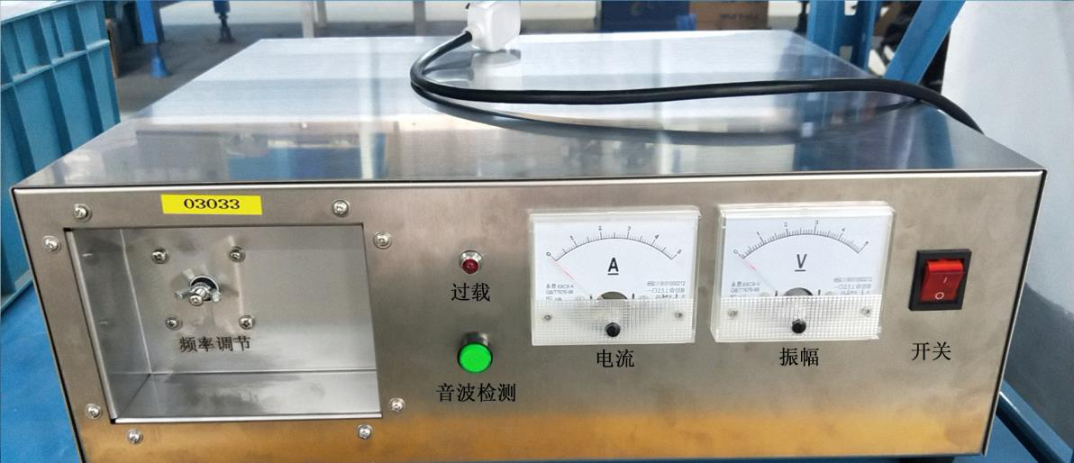
III. Description of the power supply front panel
1. Switch: power switch
2. Current: displays the operating current of the ultrasonic transducer; the normal operating current is 0.2A-0.8A, not greater than 1A;
3. Amplitude: displays the operating amplitude of the ultrasonic transducer; the normal operating amplitude is 0.2-0.8 or 2-8 (the amplitude meters of the power supply
have different scales 0~5 and 0~50), not greater than 1 or 10;
4. Overload: indicates whether an overload occurs. During normal operation the overload lamp is off; in case of overload, a red light is displayed;
5. Sonic test: press briefly or press and hold (for no more than 3s) this button; the transducer operates, and the current meter and the amplitude
meter show readings. Used to check whether the power supply output is normal;
6. Frequency adjustment: adjust with a Phillips screwdriver according to the actual welding conditions.
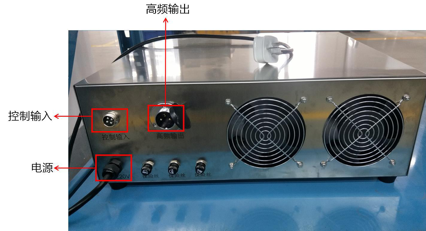
IV. Description of the power supply rear panel
1. Power: connect to the 220V 50Hz AC power supply;
2. High-frequency output: connected to the plug of the ultrasonic transducer;
3. Control input: dry contact; closed indicates that the power supply is running, open indicates that the power supply is stopped.
V. Operating steps
1. Connect the ultrasonic die to the vibrator and tighten it to form the ultrasonic transducer;
2. Install the ultrasonic transducer on the mask machine. During installation, make sure the die faces upward and contacts the mask welding roller. The contact
3. Connect the ultrasonic transducer to the high-frequency output socket on the rear panel of the power supply via the cable.
4. Insert the control signal cable plug into the control input socket on the rear panel of the power supply; the two wires at the other end (no polarity) are
5. Plug the power supply into the 220v, 50Hz AC socket;
6. Check whether the connections and wiring are correct and whether the power supply is supplying power normally.
7. On first power-up, press the sonic test button; the power supply must not be overloaded and the current and amplitude must be within the normal range (see Section
8. Turn on the front panel switch of the power supply and run the mask machine at the same time.
Note: The power supply and the ultrasonic transducer have been paired (with identical numbers) and fully adjusted before shipment, and must not be mixed.Power
supply and ultrasonic transducer are newly paired, the frequency must be readjusted; otherwise the welding result will be poor or the equipment may even be burned out.
Note: Unless necessary, do not adjust the frequency adjustment knob. Higher current or amplitude is not always better; otherwise the transduc
VI. Frequency adjustment
The power supply and the ultrasonic transducer have been fully adjusted before shipment. If the welding result is poor or the current and amplitude are too high, the frequency may be adjusted;
Note: When adjusting the frequency, the ultrasonic equipment should be in a non-operating state (i.e. the “Control input” terminal is open and there is no load on the die
1. Press briefly or press and hold (no more than 3s) sonic check, while continuously adjusting the frequency adjustment knob;
2. Under no-load conditions, observe during adjustment that the overload indicator does not alarm and that the current and amplitude remain within the normal range
3. While meeting the welding process requirements, the readings of the current meter and the amplitude meter should be as low as possible.A persistently high current
will damage the equipment.
4. If the overload lamp lights up during frequency adjustment, release the sonic check button immediately to avoid shortening the service life of the power supply or damaging inter
5. After adjustment is completed, tighten the locking knob at the bottom of the adjustment screw.
VII. Transducer usage requirements
Because the power ratings of our products are actual values, the ultrasonic vibrator and die will generate a large amount of heat during normal use. A
The manual for this product has not been uploaded yet. Please contact customer service.
Related Products
Need technical specifications and a quotation for this product?
Submit your request and our engineers will contact you within one business day.